RefWinch / Hangprinter Project
REFWINCH
An open hardware effort to make line winding more predictable, measurable, and practical in Hangprinter machines.
01 / CONTEXT
THE LARGER PROJECT
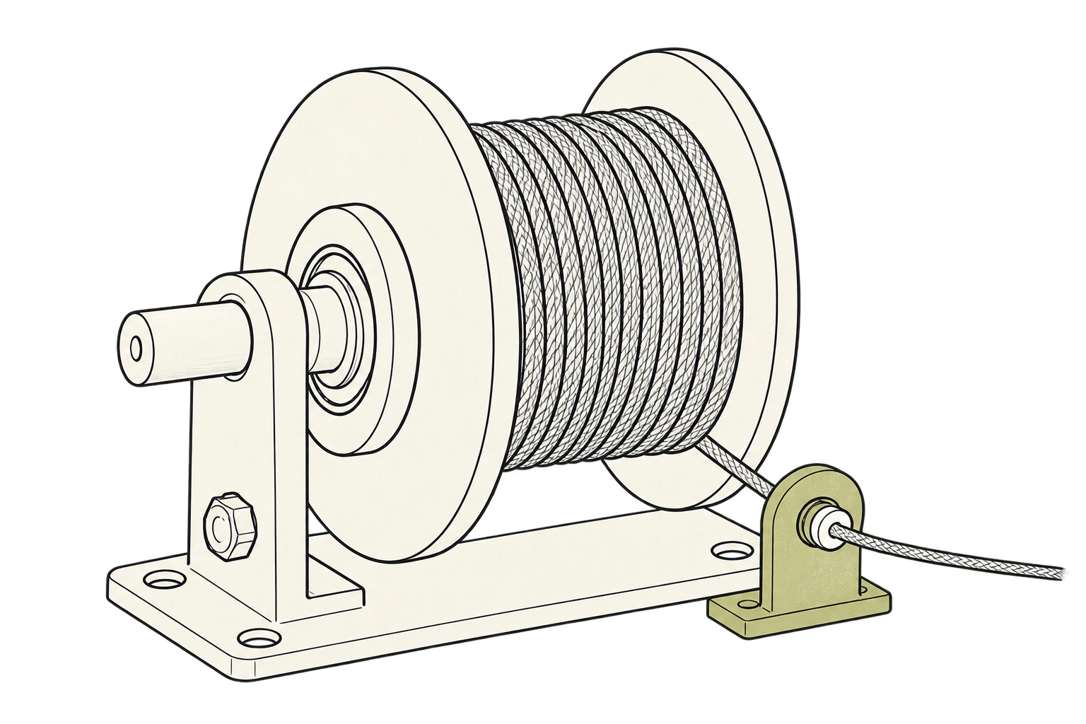
RefWinch in the
Hangprinter system.
Hangprinter is an open-source precision robot whose tool is held and moved by synchronized lines anchored around a workspace. With no heavy gantry defining the build volume, the machine can stay light, portable, and scale from a desk to a room.
Without a frame, small errors in line or belt travel can become much larger tool-position errors. Traditional gantry machines do not have the same amplification effect. So the winch is very critical to a line driven design. It also has a harder job than a typical gear or leadscrew, and a much larger space of possible solutions.
Explore Hangprinter ↗SYSTEM MAPHow winch behavior reaches the tool
CANCHOR
BANCHOR
TOOL
AANCHOR
First: COMMANDsets motor target
Then: REFWINCHdoes the winching
Then: LINE LENGTHknown change
Finally: TOOL MOVMENTto the desired position (hopefully)
02 / THE PROBLEM
WHY A REFERENCE DESIGN?
Two reasons
Small winching errors become large position errors.
Line-driven geometry can amplify small errors in winding radius, line placement, and exit position at the tool. We need winching errors to be very very small.
A mature industrial problem gets solved again and again from scratch.
Industry has many reliable winching methods. Smaller machine builders still face a large design space and often invent another good-enough solution instead of starting from a tested reference.
HANGPRINTER'S PREVIOUS APPROACHVARIABLE
Layered buildup
As line stacks, crosses, and settles, the effective spool radius changes. The machine must predict and compensate for a moving target.
- Variable transmission ratio
- Trapped slack and pile-ups
- More model uncertainty
SUGGESTED APPROACHMEASURABLE
Controlled line path
Minimize buildup and constrain the entry/exit point, so motor turns produce repeatable changes in line length that can be measured and calibrated.
- Stable transmission behavior
- Constrained cable exit
- A clean baseline to measure
The design brief turns this suggested approach into five practical requirements that different mechanisms can be tested against.
03 / DESIGN BRIEF
REQUIREMENTS
No large dent in the budget. After testing and installation, it should demand almost no attention. Low maintenance. No cable spaghetti. We want to get there via:
Predictable ratio
Near-constant, or stable enough to model, calibrate, and trust.
Stable exit point
Keep line entry and exit movement small, known, and repeatable.
Smooth, back-driveable
Winds in and out freely under controlled torque.
Low added cost
About $10 beyond the roughly $40 motor, driver, and line package.
Rigid, robust, repeatable
Holds its geometry through vibration, resonance, and fast accelerations.
04 / REFERENCE SCHEMATIC
One controlled
line path.
This simplified view shows the parts whose behavior must remain predictable, regardless of which mechanism is chosen.
FUNCTIONAL SCHEMATIC
MOTOR
CONTROLLED DRUM
↻
STABLE EXIT
05 / DESIGN SPACE
Mechanisms
under test.
The project defines the result before choosing a mechanism. Tests may favor one principle or a combination.
- 01Translating motor
The motor and drum move sideways together, following the line as it winds.
- 02Rototranslating drum
The drum rotates and slides along its axis, laying line in a controlled helix.
- 03Spline winch
A sliding drum rides on a splined shaft that keeps transmitting motor torque.
- 04Spooling helper
A separate guide moves the line across a fixed drum to prevent uncontrolled buildup.
06 / VALIDATION
Four operating conditions.
01INTIGHT LINE
The drum winds line in while external tension keeps it straight.
02INLOOSE LINE
The drum takes in slack line without letting it pile up or escape.
03OUTTIGHT LINE
The drum pays line out against a steady external pull.
04OUTLOOSE LINE
The drum feeds line out without tension, tangles, or overrun.
For all four scenarios: Does the line stay contained? Can we service the winch without unthreading? Is it cheap enough? Does it consume our time?
PROJECT SCOPE
Four Projects takes us from one actuator to a complete machine.
Prove one repeatable line-length actuator. A physical one. No sim.
Combine reference winches in a desktop test rig.
Scale the verified motion system into open, large-volume fabrication.
PROJECT LINKS